Outputs
Here you will find the current context structure.
![]() Geometry
Geometry
This is the position of the currently rendered position on the surface in the global coordinates.
This is the normalized direction from which the. incoming ray originated.
This is the global start position of the render sample currently being calculated. This is, as a rule, identical to the position of the active render camera.
This is the Normal direction prior to applying Bump or Normal mapping.
This is the final Normal direction at the point currently being rendered as is defined after the Bump and/or Normal Map, Phong tag or Normal tag has been evaluated.
Here you will find the original Normal direction as is defined by the polygon’s position.
The calculation of the surface Normals is based on the point of intersection between two edge directions of a polygon. This calculation is, however, not enough to get a smoothed Normal because the surrounding polygons must be included in the calculation. For this purpose, curves will be generated that run in the U and V directions. Tangents can be generated along these curves that will produce smoothed Normals at every location on the surface. The Tangent output displays the tangent in the U direction.
This tangent represents the tangent in the V direction.
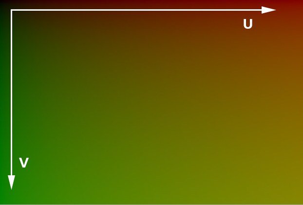
These are the unmodified UVW coordinates of the surface at the point currently being rendered.
These are the UVW coordinates – possibly modified via the Context input – at the point currently being rendered.

Barycentric coordinates are an alternative coordinate system that spans the plane of a given polygon. The origin of this axis system lies at the cener of gravity of the respective triangle or quad. Positions within the polygon can be defined based on their distance from the borders or surfaces that limit them. In this case, the position of the rendered point is defined relative to the cener point of each polygon.
RELEASE 21
Vertex A [XYZ ]
Vertex B [XYZ ]
Vertex C [XYZ ]
Vertex D [XYZ ]
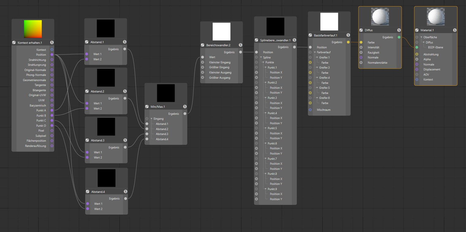
 With the output for the point positions at the currently calculated polygon, shaders can be created that react to surface points.
Here, up to 4 global positions of the corner points are output at the currently calculated polygon. For triangles, the positions for Point C and Poing D are identical.
![]() Pixel
Pixel
Here the coordinates of the currently rendered pixel will be output. The values returned are in relation to the absolute rendering resolution and go beyond one.
For sampling, multiple render rays have to be emitted to different locations within a pixel. Sub-Pixel defines the position of the sub-pixel currently being rendered.
 The position of each surface point can also be output relative to the image coordinates, via the surface position. This coordinate system has its origin at the top left corner of the image and is therefore independent of the position of the textured object.
These coordinates output the position of each surface point relative to the image coordinates. The image coordinate system has its origin at the top left corner.
Outputs the render resolution currently being used from the active Render Settings.